What Are Location Tabs And Why Do You Use Them?

Location tabs can be used on a tool and / or part for locating & loading a part to a trim fixture, inspection fixture, or for mounting a part within a composite structure for bonding or assembly purposes. Often, these location tabs are sacrificial and an “Add-on” to the existing ply structure of that part. These Locational tabs offer the fabricator a means of locating pertinent aspects of the part to another mating surface or to achieve dimensional stability and a high degree of repeatability in manual or CNC trim operations. In manual trim operations, the location tab in the part will mate to the “trim tool” for an accurate cut to be made. (usually with a ~.030” offset so one doesn’t scuff the trim tool) Locational tabs in the part may also be used in assembly operations as the part’s tab will fix the position into assembly jigs used for adding hardware or other needed additions to an existing component.
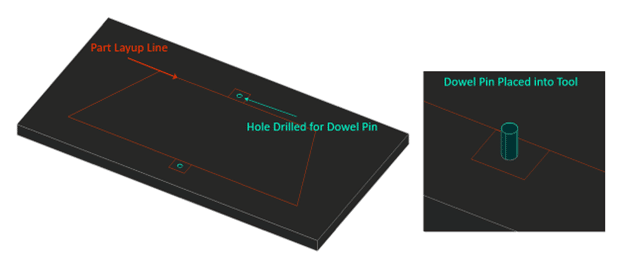
A location tab is usually incorporated into a layup tool / mold by extending the layup surface of a mold by a couple inches and leaving a marking area or hole in the area to which it will be located to in the future. (As shown as the squared off area on each side of the above illustration) One way this can be achieved by placing a sleeve and extractable dowel pin into the layup mold. In metal molds this is common practice for composite parts. In composite molds, it is not too much different. Sleeves & Dowel pins can be purchased from several sources. McMaster-Carr (online) will usually have any size needed. For purposes of standardizing, the same pin diameter size will need to be used throughout the locating tools. For most practical purposes, a 1/4” dowel pin will suffice for needed projects.

Dowel pins can be added to a layup mold multiple way. For simplicity purposes for most DIY projects, one can simply add a sleeve and a dowl pin into a thicker region of the tool beyond the layup line. Start by drilling a hole for the sleeve to go down into. Drill a hole approximately the same diameter as the outer diameter of the sleeve. Drill into the tool about the same depth as the sleeve. Hammer or Press the sleeve into the mold surface then hammer the dowel pin in using a rubber mallet. Use of a metal hammer would not be advised as the energy is reflected upon the tool when hitting the dowel pin in. It is best practice to place at least (2) sleeves / dowel pins in the tool for the part to be located properly. One locational tab will not work in most cases. BE SURE TO ADD MOLD RELEASE TO THE SLEEVES & DOWEL PINS! A drill stop should be used in the demold / hole drill process so that the drill bit does not go too deep into the tool.

Once the dowel pins are placed. Add fabric layers to surrounding the dowel pin as shown below. Extend the sacrificial plys ~1.00” beyond the dowel pins. Cut a slit into the plys so that the plys lay down onto the tool and provide a means of stripping them off later. Once the part is laid up and cured, simply pop the part off the mold and there will be a hole for locating the parts as needed.
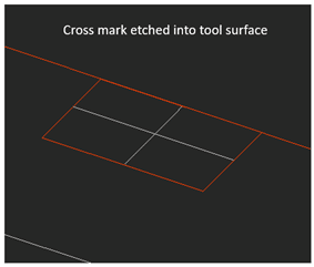
Another option some may find as easier, is placing a locating feature on the mold surface for the part to be drilled after cure and stripping. This may be achieved by marking the tool beyond the layup surface with a cross pattern. Showing where the cured part can be drilled to provide a locating feature. This of course will “damage” the tool in a way as there will be but will not affect laminate quality. This option is quicker than a dowel pin but may not be as accurate from human aspect of manually drilling holes at consistent angles. Simply add sacrificial layers of fabric and resin to the locational tab area and allow vacuum pressure to supply an imprint to the final part.

The third option of adding locational tabs to a part is to add a jig feature to the tool using a dowel pin as a locating means. As shown above, an inserted sleeve / hole (as described above) will position a drill fixture on a specified area beyond the trim line of the part. The jig will be placed down onto the tool and a hole can be drilled in place to the tool. To achieve this, a drill hole will need to be added to the tool. But NOT ALL THE WAY THROUGH the layup mold. Simply do as instructed above with adding a sleeve into the tool. A drill stop should be used so that the drill bit does not go too deep into the tool.

File Type: pdf
Categories: Composite Techniques, General Composite Knowledge, Tips & Tricks

Share:

Back to Knowledge Hub

Compare Products